Stay up to date with Tempo Announcements and News

Line Locators: Application & Usage Guide
Line Locators: Application & Usage Guide
Locating underground assets such as cables and pipes is part science and part art, and the challenge only increases when searching for points of interest, such as joints and tees. We’ll show you the equipment and techniques to detect what’s beneath your feet.
Reasons to Locate: From Finding Faults to Damage Prevention
You may be locating to determine where you need to dig or where NOT to dig! You could be searching for something you need to excavate to make a modification, repair, replacement, or removal, or you may simply need to know where you are free to bury a new addition without risk of hitting something dangerous or expensive.
Safety and Damage Repair


Striking utility lines can create dangerous situations including explosions, electrocution hazards, or high-pressure jets of water that put lives at risk.
Besides the destructive nature of gas, power, and water, even telecommunications lines require a great deal of manpower and equipment to bring back online if they are damaged Thus, the importance of locating buried utilities is widespread across all underground assets.
Access
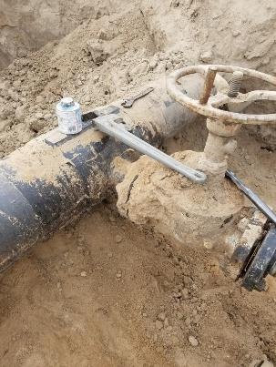
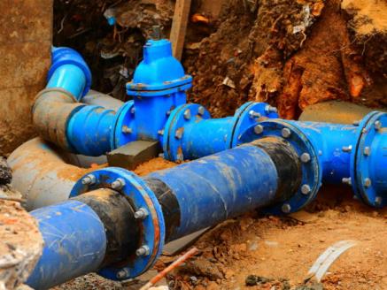
There are points along buried lines that may need to be uncovered and manipulated by hand such as damaged lines, valves, or joints/fittings.
Line Locators: Transmitting and Receiving Signals
Metal cables and pipes are conductive and well-suited for carrying electricity. We can apply alternating currents of electricity to these metallic lines to “sense” where they are located and which direction they travel.
Line locating often relies on understanding how well a circuit can be made using the line being located and the surrounding soil. Changes in signal application method, positioning of the transmitter along the line, signal frequency, and even ground stake placement can all influence how well your signal corresponds to the line you’re locating.
Having a basic understanding of electromagnetic fields and antennas can enhance your ability to interpret signal sources beneath your feet.

Transmitter Signals – Alternating Currents at Different Frequencies
Circuits
Signals can be thought of as rapid “vibrations” of electricity that travel out from the transmitter along a metallic line and are strongest when they can most easily move in a circular path back to the transmitter via ground stake.

Earth (dirt/clay/sand) that contains moisture is conductive, so if the far end of the line comes into electrical contact with the earth, a simple circuit is created: out along the line, back through the earth in a widespread area and then concentrating around the transmitter’s ground stake once again.

Even without direct electrical contact on the far end, the signal can capacitively “leak” little by little along the conductor and return to the transmitter through the earth and eventually back through the ground, creating little circuits of electricity along the way.

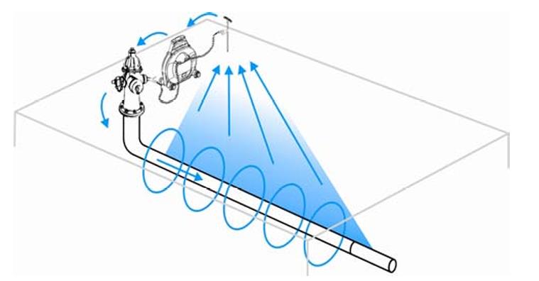
The longer the buried line extends away from you and the transmitter, the more signal will be carried through the portion of the line underneath you.
If you can, it is always better to ground the far end of the cable than to rely on capacitive leakage.
Frequency
This capacitive leakage or sometimes called “bleed” effect into the dirt increases as the frequency of your signal increases, so higher frequencies work well to travel along shorter lines as well as lines that are not directly grounded at the far end. The drawback is that a high-frequency signal generally won’t travel as far as a low-frequency signal.
In fact, there are other tradeoffs you can make with higher or lower frequencies:

Higher frequency signals “bleed” not only to the ground but to other nearby conductive lines. This means you may detect signal on a nearby pipe, cable, rebar, or metal fence even though they’re not connected to the transmitter.
Higher frequencies can also “bleed” through poor conductivity due to corrosion, bad connections, or even non-metallic gaskets. This can work in your favor when tracing damaged lines but against you when trying to pinpoint where the damage is located. Use the lowest frequency available to avoid “bleed” and to trace as far as possible, particularly when you have grounded the far end of a cable.
Locator frequencies tend to range between around 500 Hz (cycles per second) on the lowest end and around 500,000 Hz (500 kHz) on the highest end). This is a logarithmic scale, so 1.75 kHz, 33 kHz, and 447 kHz are all roughly equally spread.

Grounding
Even the wettest dirt is not nearly as conductive as metal. Still, there is just so much dirt in the ground that electricity usually has no problem moving through it unless it’s very rocky, loose, dry, frozen, or a combination thereof. Attaching one of the transmitter’s leads to the line and the other to the earth via a Ground Stake is usually the most effective and efficient way of applying signal to a line.
The ground stake connected to the transmitter sometimes causes a bottleneck in the signal circuit. There is a limited amount of dirt touching the surface area of the metal stake, so driving the ground stake as far into the dirt as possible and wetting the dirt around the ground stake can have a positive effect. But use care, you are pushing a sharp spike into the soil; do you know there’s nothing dangerous under there?

Even moving the ground stake from one spot to another can improve signal. It’s best to start with the ground stake a few feet off to one side of the buried line. Avoid placing the ground stake on the far side of any other buried lines in the area to avoid signal bleeding onto those lines.
Induction
Directly connecting to a line is preferred, but it’s not always possible. Since signals can “bleed” over to other lines, especially higher frequencies, we can use this to our advantage and “wirelessly” induce signals onto a line.
By coiling wire, you can multiply the magnetic field and “broadcast,” making it possible to induce a signal to a line below ground that you don’t have direct access to.
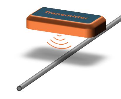
Furthermore, creating an inductive antenna in the shape of a loop can more efficiently induce signal onto a line without needing to access the metallic portion. These Inductive Coupler Clamps can be very handy when cables are insulated or protected by plastic conduit. Not only that, but signals can even be safely applied to power lines carrying live voltage or signal cables that are in operation.

Directly connecting to a line will always give the strongest signal, followed by an Inductive Coupler Clamp, and lastly with a Broadcast Antenna. Keep in mind that it’s more difficult to use lower frequencies when using inductive methods, so you won’t have their long-distance and low-bleed benefits.
EM Fields
Locator signals are alternating currents that cause electromagnetic fields to alternatearoundthe lines they travel through.

This alternating electromagnetic field that an antenna can pick up is strongest nearer to the line and can also get stronger as more signal current flows through the line; hence why it is always best to ground the far end of the cable if you can.
Receiver Antennas – Cylindrical Coils

Receiver antennas are essentially small coils of wire wrapped into cylindrical shapes that detect electromagnetic vibrations moving across them.
Peak Antenna
This means the most signal an antenna can receive is when the coil cylinder is oriented perpendicular to the line, as shown above. The “loops” of the magnetic field around the conductor pass directly along the main axis of the coil generating the strongest signal.

Null Antenna
If the coil cylinder is oriented 90 degrees so that it is vertically pointed directly at the line above it, there are no magnetic field lines moving along the cylinder, and it receives no signal whatsoever.

If the antenna drifts slightly from this alignment, small amounts of signal will be received, so it is easy to tell when the antenna is pointed directly at the line.
Another Null
Keeping the Peak Antenna horizontal but twisting it around to be parallel with the line will also result in a Null (signal cancellation). This helps determine the direction of the line.

When using a Line Locator’s Receiver, remember that you may sometimes need to visualize not just the line but the interaction of the antenna with the round field lines around the line.
Depth/Current
Since Null antennas are very precise, one can triangulate the depth of a line quite accurately using only a Null antenna. When holding the Receiver vertically, a Null indicates the line is directly below. Finding the Null again at a 45-degree angle creates an imaginary triangle where the distance between the two points on the ground equals the depth of the line.

Sophisticated Line Locators will have Receivers with multiple Peak antennas stacked upon one another at set distances. With multiple antennas receiving different amounts of signal, the Receivers can compute not only the depth of the line but also the amount of signal current running through it.

Buried Markers: Highlighting Points of Interest
Many buried services are non-conductive; plastic gas and water pipes, optical fiber cables, concrete rainwater drains etc. Often these have been installed with “tracer wires” specifically buried directly above them for the past couple of decades, however, earlier ones may not have such aids. Also, when repairs are made do those tracer wires get reconnected reliably? Often not.
For electrical and telephone cables, being able to follow the signal from above ground can tell you the depth and position of the conductor underground but cannot identify where, for example, a buried splice joint is located.
Or for plastic pipelines, even if buried with tracer wire, it’s not good enough to know where a line is located and in which direction it’s going; you may also need to know where an access point to a shutoff valve is or where a repair was performed. Buried passive electronic markers put you back exactly where you need to be and will last as long as the buried assets they’re marking.
Points of Interest
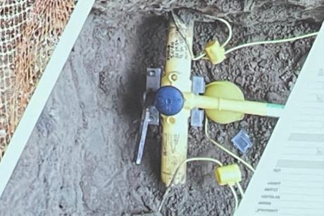


Many points along a utility line are of interest to utility companies or to anyone avoiding damage when digging, which won’t necessarily be locatable with a Line Locator alone:
Joints/Fittings
Wyes/Tees
Curves/Bends
Stubs/Ends
Depth Changes
Material Changes
Repairs
Valves
Resonant coils
Coming in various shapes, passive electronic buried markers are a clever technology that does not require any battery power but can still be detected multiple feet deep using coils tuned to resonate at specific frequencies when excited by a marker locator from above.


Fields
These resonant coils create electromagnetic fields that give off a hot spot for Marker locators. Some markers need to be placed vertically to ensure a field is directly above (e.g., spike markers), some need to be placed flat (e.g., disk markers), while others are self-leveling (marker balls).


Frequencies
There are different tuned frequencies for different color markers, each corresponding to a type of utility or asset:
Purple, Non-Potable Water, 66.35kHz
Orange and Black, CATV, 77kHz
Yellow, Gas, 83kHz
Yellow/Black, Fiber Optic, 92kHz
Orange, Telephone/Communications, 101.4kHz
Green, Sanitary, 121.6kHz
Red and Blue, Power (Europe), 134kHz
Blue, Water, 145.7 kHz
Red, Power (North America), 169.8 kHz
With a little bit of forethought, you can bury passive electronic markers and leave all the clues you need to pinpoint exactly what it is you may come back to search for.
Other Location Methods: From Pseudoscience to Cutting Edge
The vast majority of professional utility locators use transmitter/receiver line locators to do their work, and between line locators and buried markers, you can find just about everything you’d ever need to look for. Still, there are some other “technologies” out there as well.
“Witching” Sticks/Divining Rods
There is no scientific basis for it, and who knows how it began, but over thousands of years, people have believed that Y-shaped or L-shaped sticks would lead them to water, or other types of lines buried in the ground. Many folks today claim to be highly accurate and reliable with “witching” or “divining,” but you won’t find too many Utilities putting their trust in this method of locating.

Metal Detectors
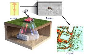
Metal detectors use various technologies that are very helpful in finding buried metal objects of all kinds. Because they find any metals, including random objects, Utility Locators will often use them with Ground Penetrating Radar (GPR).

Ground Penetrating Radar
A very effective and versatile tool for underground locating, GPR can find lines and objects that are metal or non-metal alike. The reason GPR is not used more often is the combination of being costly and producing data that is difficult to interpret.
Acoustic Resonating Locators (for locating non-metallic pipes like PVC)
A low-cost solution, Acoustic Locators allow users to find lines by ear. They have a limited range but work quite well for short water lines.

Electrical Resistivity Tomography
One of the most sophisticated Underground Locating technologies, ERT will inject electrical current into the ground and measure variations in the earth’s resistivity, which paints a picture of the underground, from rock formations to groundwater locations to Utility and Infrastructure mapping. This technology is even more expensive and difficult to interpret than GPR while being substantially more difficult to set up.

Conclusion
Locating underground assets is both a science and an art, at times requiring an understanding of electrical circuits, signal behavior, and field interactions. Whether you’re preventing damage, accessing key points for repair, or mapping buried infrastructure for future use, the right tools and techniques make all the difference. By leveraging the various complementary electromagnetic locating methods, buried markers, and emerging technologies, professionals can efficiently and accurately detect what’s hidden beneath the surface. While some traditional methods persist, modern advancements continue to refine and expand the capabilities of utility locating, ensuring safety, efficiency, and precision in every dig.
